


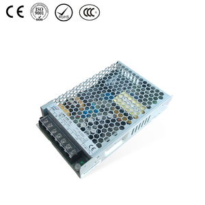
24V DC Power Supply Voltage Drop: Causes, Troubleshooting, and Prevention
Date:2026-11-14 01:39:49 Visit:29
A 24V DC power supply is widely used in industrial automation systems, PLC control cabinets, sensors, relays, solenoid valves, and other electrical equipment. However, even when a power supply is rated at 24V, the voltage measured at the connected device may be lower than expected.
This condition is known as voltage drop.
A significant voltage drop can cause PLC communication errors, sensor malfunctions, relay chatter, solenoid valve failures, and unexpected equipment shutdowns. In many cases, the problem is not caused by a defective power supply. Instead, it may result from undersized cables, excessive cable length, loose connections, overloaded circuits, or poor power distribution design.
This guide explains the common causes of 24V DC voltage drop, how to calculate it, how to troubleshoot low voltage, and how to select a suitable industrial 24V DC power supply.
1.What Is a 24V DC Voltage Drop?
Voltage drop is the reduction in electrical voltage that occurs when current flows through a wire or electrical connection.
In a typical 24V DC industrial system, the power supply delivers 24V DC to connected equipment through two wires.
Every wire has a certain amount of electrical resistance. When current passes through the wire, a small amount of voltage is lost along the way.
Therefore, the voltage measured at the equipment may be lower than the voltage measured directly at the power supply output terminals.
2. How to Calculate 24V DC Cable Voltage Drop
Calculating voltage drop before installation helps engineers select suitable cables and avoid unexpected low-voltage problems.
For a DC circuit with separate positive and negative conductors, use:
Voltage Drop = Current × Total Cable Resistance
The total cable resistance includes both the outgoing and return conductors.
For a uniform copper cable:
R = 2 × ρ × L / A
Where:
-
R = Total cable resistance (Ω)
-
ρ = Copper resistivity, approximately 0.0175 Ω·mm²/m at 20°C
-
L = One-way cable length (m)
-
A = Cable cross-sectional area (mm²)
The voltage drop is:
Vd = I × R
The percentage voltage drop is:
Voltage Drop (%) = (Vd / 24) × 100
Practical Calculation Example
Suppose an industrial control system has the following requirements:
-
Supply voltage: 24V DC
-
Load current: 2A
-
One-way cable length: 20m
-
Cable material: Copper
-
Cable cross-sectional area: 1.5mm²
Step 1: Calculate total cable resistance.
R = 2 × 0.0175 × 20 / 1.5
R ≈ 0.467Ω
Step 2: Calculate voltage drop.
Vd = 2 × 0.467
Vd ≈ 0.934V
Step 3: Calculate the voltage at the load.
24 - 0.934 = 23.066V
Step 4: Calculate the percentage voltage drop.
(0.934 / 24) × 100 ≈ 3.89%
The connected equipment receives approximately 23.07V DC under the assumed operating conditions.
This calculation is an estimate based on copper conductor resistance at 20°C. Actual voltage drop may be higher because of increased conductor temperature, terminal resistance, connectors, fuses, and other circuit components.
Engineers should verify the final cable selection using applicable electrical standards, cable manufacturer data, installation conditions, and the connected equipment's minimum voltage requirements.
3. How to Troubleshoot a 24V DC Power Supply Voltage Drop
If an industrial system experiences low voltage, follow a systematic troubleshooting process instead of immediately replacing the power supply.
Step 1: Measure Voltage at the Power Supply Output
Use a suitable digital multimeter to measure the DC voltage directly across the positive and negative output terminals.
Check whether the voltage is close to the specified output value.
If the voltage is already low at the power supply terminals, investigate:
-
Input AC or DC voltage.
-
Total connected load.
-
Overload protection.
-
Power supply temperature.
-
Output terminal connections.
-
Power supply condition.
Step 2: Measure Voltage at the Load
Measure voltage directly at the terminals of the connected equipment while the system is operating.
Compare this measurement with the voltage measured at the power supply.
A significant difference indicates voltage loss somewhere along the distribution circuit.
Step 3: Measure Under Actual Operating Load
Do not rely only on no-load voltage measurements.
Some voltage problems occur only when equipment starts or when multiple devices operate simultaneously.
Measure the voltage under:
-
Normal operating conditions.
-
Maximum expected load.
-
Startup or peak-load conditions, where applicable.
Step 4: Inspect Wiring and Connections
Check for:
-
Undersized conductors.
-
Excessive cable length.
-
Loose terminal screws.
-
Corroded connectors.
-
Damaged insulation or conductors.
-
Poor distribution connections.
For intermittent problems, monitor the voltage during the operating event that triggers the fault.
Step 5: Check Power Supply Capacity
Calculate the actual load demand and compare it with the rated output current and power of the power supply.
If the system operates close to or beyond its rated capacity, consider selecting a power supply with suitable additional capacity, subject to the manufacturer's derating and application requirements.
Step 6: Verify Equipment Voltage Requirements
Different PLCs, sensors, relays, and actuators may have different operating voltage ranges.
Check the equipment datasheets rather than assuming that every device operates correctly at the same minimum voltage.
A voltage level that is acceptable for one device may cause another device to malfunction.
Important safety note: Measurements and repairs should be performed by qualified personnel using appropriately rated instruments and safe electrical procedures.
4. How to Choose a Reliable 24V DC Power Supply for Industrial Applications
Choosing the right power supply is essential for maintaining stable voltage in industrial automation systems.
Before selecting a 24V DC power supply, evaluate the following factors.
Output Voltage and Rated Current
Confirm that the output voltage matches the requirements of the connected equipment.
Calculate the total load current and verify that the rated output current is sufficient.
For example:
-
24V × 2.5A = 60W
-
24V × 5A = 120W
-
24V × 10A = 240W
These ratings illustrate the relationship between output voltage, current, and power. Actual product selection must also consider operating conditions and derating.
Input Voltage Range
Check the available AC or DC input voltage at the installation location.
A suitable input voltage range helps ensure compatibility with the electrical supply.
Protection Functions
Depending on the application, useful protection functions may include:
-
Short-circuit protection.
-
Overload protection.
-
Overvoltage protection.
-
Overtemperature protection.
Always verify the actual protection functions in the individual product datasheet.
Installation and Cooling
Consider the available cabinet space, mounting method, ventilation, and ambient temperature.
A DIN rail power supply can simplify installation in industrial control cabinets.
Output Regulation and Voltage Adjustment
Check voltage tolerance, load regulation, and available output adjustment range.
These specifications help engineers evaluate whether a power supply is suitable for applications requiring stable DC voltage.
5. LEYU 24V DIN Rail Power Supply Solutions
For industrial automation and control cabinet applications, LEYU offers a range of 24V DIN rail power supply options.
Different output ratings can be selected according to the load requirements of the application.
Examples include:
LEYU ZDR5-120
-
Output voltage: 24V DC
-
Rated current: 5A
-
Rated output power: 120W
-
Voltage adjustment range: -10% to +15%
-
Voltage tolerance: ±1%
-
DIN rail mounting
LEYU ZDR5-240
-
Output voltage: 24V DC
-
Rated current: 10A
-
Rated output power: 240W
-
Voltage adjustment range: -10% to +15%
-
Voltage tolerance: ±1%
-
DIN rail mounting
These models offer different output capacities for industrial control and automation applications.
The correct choice depends on the total load current, installation environment, input voltage, and system design.
For more information:
LEYU also provides switching power supply solutions for different industrial applications, with OEM and ODM customization support.
Contact LEYU to discuss your required output voltage, current, input range, and installation conditions.
