


-134213.jpg)
How to Safely Connect a Switching Power Supply Module to Mains Power: A Complete, Step-by-Step Guide
Date:2026-07-18 10:02:33 Visit:654
I. A Maker's Afternoon
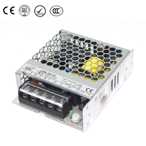
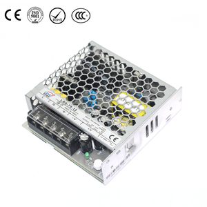
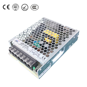
John, a robotics enthusiast, recently designed a wheeled chassis that requires a 24V/5A DC power supply. He purchased a switching power supply module online—the kind with a perforated metal casing and screw terminals, often marketed as "industrial-grade." Upon receiving the package, he skillfully grabbed a screwdriver to begin wiring; connecting the output to the motor controller was straightforward enough. However, when he turned his attention to the input terminals, he was stumped by the markings: "L," "N," and a symbol resembling an inverted trident."I know the plug goes into the wall, of course, but which pin does each wire correspond to? How do I interpret the wire colors? What if I wire it incorrectly—will it explode?"
Many hobbyists encountering this type of power supply for the first time have likely faced the same confusion. Today, let’s clear this matter up once and for all.
II. Understanding the Input Terminals of Your Switching Power Supply
On most commercially available AC-DC switching power supplies (such as models designated "S-350-24"), the input terminals are located on the left or right side and are marked with three screw terminals:
L Live The phase wire carrying AC voltage
N Neutral The return wire that completes the circuit
⏚ or ⊥ Earth/Ground Conducts excess current and the chassis connection to the ground to prevent electric shock
⚠️ Note: Some power supplies may use labels such as "L," "N," "GND," or "FG" (Frame Ground), but the functions remain identical.
These three terminals must be connected to the corresponding three pins of the power plug; once the plug is inserted into a wall outlet, mains power enters the power supply through them.
III. Preparing Tools and Materials
Before you begin, ensure you have the following items on hand:
A power cord.Wire strippers (for removing the outer sheath and insulation).
Crimping tool (if using crimp terminals).
Insulated crimp terminals (fork or ring type; sized to fit the terminal screws, typically M4 or M5).
Multimeter (essential! Used to verify which wire corresponds to which plug pin).
Screwdriver (for tightening terminal screws).
Insulated housing or protective cover (the metal parts of the power supply itself are live and must be enclosed).
Heat-shrink tubing or electrical tape (for additional insulation).
💡 Easiest? Get yourself a cheap or free computer cord. They happen at $1 prices.
IV. Step-by-Step Wiring Guide
Step 1: Cut the cable and strip the outer sheath
Cut off one end of the power cord (the end that connects to the device), keeping the section with the plug. Use wire strippers to remove about 5–8 cm of the outer sheath, exposing the three internal wires (which are typically color-coded). Then, strip approximately 1 cm of insulation from each wire to expose the copper core.Step 2: Identify the true function of the three wires
Never rely solely on color! Standards for wire colors vary by country and manufacturer, and internal wire coloring can sometimes be inconsistent.
Common standards are as follows (for reference only):
Region Ground Wire Neutral Wire (N) Live Wire (L)
North America (Old) Green White Black
North America (New) Green/Yellow stripe White Black
Europe / IEC Green/Yellow (dual-color) Light Blue Brown
China (GB) Yellow/Green (dual-color) Light Blue Brown
Best practice:
Set your multimeter to the resistance (or continuity) mode and insert the plug into the socket (but do not connect the power! This is solely for testing continuity). Touch one probe to the plug's ground pin (the longest round pin, or the one isolated from the other two) and use the other probe to touch each of the three exposed wires in turn; the wire that shows continuity is the ground wire. Similarly, touch the probes to the left pin (narrow or wide, depending on the specific plug type) or the right pin to distinguish between the Neutral (N) and Live (L) wires.🔴 Highly recommended: Use a multimeter set to continuity mode (buzzer) to identify the connector pin corresponding to each wire, and mark them clearly (using labels or other markings).
Step 3: Crimp the insulated terminal
While simply wrapping bare copper wire around a screw post can conduct electricity, the connection is prone to loosening and poor contact, and may even spark. The correct approach is to use a crimp terminal.Select a spade or ring terminal that matches the screw diameter.
Insert the copper conductor into the terminal's barrel and crimp it securely using crimping pliers (paying attention to the crimping position and force).
Gently pull on the wire to ensure it does not come loose.
Step 4: Connect to the power supply module in the correct order
Connect the wires (with terminals already attached) to the corresponding screw terminals:
Ground wire → Connect to the terminal marked ⏚ or FG (usually the middle screw).
N (Neutral wire) → Connect to the terminal marked N.
L (Live wire) → Connect to the terminal marked L.
Tighten the screws with moderate force; ensure good metal-to-metal contact without stripping the threads. If using ring terminals, remember to pass the screw through the ring opening before tightening.
Step 5: Install the protective cover and housing
Most switching power supply modules come with a transparent plastic cover for the terminal area. After wiring is complete, be sure to reinstall this cover to shield all exposed high-voltage points. If the power supply is to be installed inside a metal chassis, the unit's ground terminal must be securely connected to the chassis (using a dedicated grounding bolt), ensuring the entire system is properly grounded.
Step 6: Final Check (Before Powering On)
Before plugging the unit into the power outlet, perform the following checks:Use a multimeter set to the resistance range to check for short circuits between L and N, L and Ground, and N and Ground (normal readings should show some resistance, not 0 Ω).
Check that all screws are tightened and ensure no bare copper strands are protruding from the terminals.
Verify that no metal parts of the casing are in direct contact with internal live components.
Confirm that the power supply output (DC side) is not connected to any load (perform a no-load test first).
Only after confirming everything is correct should you plug the unit into the outlet and power it on.
