



How to Calculate 24V DC Power Supply Requirements for a PLC Control Cabinet
Date:2026-10-31 01:19:26 Visit:23
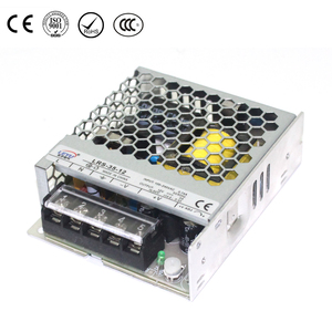
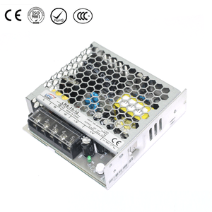
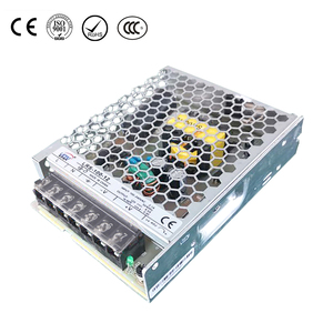
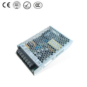
A 24V DC power supply is widely used in industrial PLC control cabinets to provide power to control circuits, sensors, relays, communication devices, and other field equipment.
However, selecting the right power supply is not simply a matter of checking the PLC's rated power. Engineers must first identify which devices are supplied by the external 24V DC power source, calculate their total current demand, and then consider startup current, operating conditions, temperature derating, and future expansion.
An undersized power supply may cause output voltage drops, unexpected equipment resets, or intermittent control-system faults. An unnecessarily oversized unit may increase cost and occupy valuable cabinet space.
This guide explains how to calculate the required 24V DC power supply capacity for a PLC control cabinet, including a worked example, practical selection considerations, and a final engineering checklist.
1. Understand 24V DC Power Distribution in a PLC Control Cabinet
Before calculating the required power supply capacity, it is important to understand how power is distributed inside the control cabinet.
A typical PLC control system may include:
- PLC CPU and expansion modules
- Digital and analog I/O devices
- Proximity and photoelectric sensors
- Electromagnetic relays and contactor coils
- Solenoid valves
- HMI panels
- Industrial Ethernet switches
- Other 24V DC field devices
Although these devices may be part of the same control system, they do not necessarily draw power from the same source.
Some PLCs have internal power supplies or backplane power arrangements for their CPU and expansion modules. Other devices may require an external 24V DC supply.
For this reason, do not automatically add the power consumption of every PLC module to the external power supply calculation.
First, check the PLC manufacturer's system manual, wiring diagrams, and power-budget specifications.
For example, Siemens SIMATIC S7-1200 documentation distinguishes between internal system power and external sensor supply requirements. The available power for connected devices must be checked against the specifications of the particular CPU and module configuration.
Important: Only include the loads that are actually powered by the external 24V DC supply. Avoid counting the same power consumption twice.
2. Identify All External 24V DC Loads
The first practical step is to create a load list.
For every device connected to the external 24V DC power supply, collect its electrical specifications.
| Rated voltage | Confirm that the device is designed for the required DC voltage |
| Rated current | Identify its normal operating current |
| Rated power | Check the manufacturer's specified power consumption |
| Startup current | Determine whether the device draws additional current during startup |
| Operating mode | Identify continuous, intermittent, and simultaneous loads |
| Quantity | Count the number of identical devices |
| Supply source | Confirm that the device is powered by the external 24V DC supply |
Whenever possible, use the manufacturer's rated input current rather than estimating current from a general power figure.
If only the rated power is available, current can be estimated using:
I = P / V
Where:
-
I = Current in amperes (A)
-
P = Power in watts (W)
-
V = Voltage in volts (V)
For a 24V DC system:
Current (A) = Power (W) / 24V
For example, a device with a 12W input power requirement at 24V DC draws approximately:
12W / 24V = 0.5A
This is a basic calculation. If the manufacturer specifies input current directly, use that value and follow the stated operating conditions.
3. Calculate the Total Normal Operating Current
After identifying all external 24V DC loads, calculate their combined normal operating current.
The basic formula is:
I_total = I₁ + I₂ + I₃ + ... + Iₙ
Where each current represents an individual device or load group.
For devices with identical ratings:
I_group = Quantity × Current per Device
For example, if 12 sensors each draw 30mA:
12 × 0.03A = 0.36A
The following example demonstrates how to organize a load calculation.
4. Worked Example: 24V DC Power Supply Sizing for a PLC Cabinet
Assume a hypothetical PLC control cabinet uses one external 24V DC power supply for the following equipment.
The values below are illustrative assumptions for explaining the calculation method. They are not measured specifications for a particular PLC, sensor, or LEYU product.
| External 24V DC Load | Quantity | Current per Unit | Total Current |
|---|---|---|---|
| PLC external 24V DC input | 1 | 0.40A | 0.40A |
| Proximity sensors | 12 | 0.03A | 0.36A |
| Relay coils | 8 | 0.04A | 0.32A |
| HMI panel | 1 | 0.50A | 0.50A |
| Industrial Ethernet switch | 1 | 0.25A | 0.25A |
| Total | 1.83A |
In this example, the total normal operating current is:
I_total = 1.83A
At a nominal output voltage of 24V DC, the corresponding power is:
P = V × I
P = 24V × 1.83A
P = 43.92W
Therefore, the external 24V DC supply must provide at least 1.83A under the assumed normal operating conditions.
This calculation does not include any PLC backplane or internally supplied module loads. Those must be checked separately against the PLC manufacturer's power-budget specifications.
5. Allow for Additional Capacity
Selecting a power supply with exactly the calculated normal load capacity leaves little room for load variation or future changes.
A design reserve may be required, but there is no single power margin suitable for every PLC control cabinet.
The required reserve should be determined from:
-
Normal operating load
-
Startup and transient demand
-
Simultaneous operation of connected devices
-
Expected future expansion
-
Ambient temperature and derating
-
The power supply manufacturer's specifications
For this illustrative example, assume a preliminary 25% design reserve is appropriate.
Required Current = Normal Load Current × 1.25
1.83A × 1.25 = 2.2875A
The corresponding nominal output power is:
24V × 2.2875A = 54.9W
A 24V DC, 3A power supply has a nominal rated output of:
24V × 3A = 72W
It could be a candidate for this example, provided that its actual usable output capacity remains sufficient after checking startup demand, ambient-temperature derating, and other installation conditions.
The 25% figure is only an illustrative design assumption. It should not replace an assessment of actual load behavior or the manufacturer's technical requirements.
6. Check Startup Current and Peak Load Demand
Normal operating current is not always the maximum current required by the control cabinet.
Some electrical devices draw additional current when they are energized or switched on.
Examples include:
-
Relay and contactor coils
-
Solenoid valves
-
Capacitive electronic loads
-
Communication equipment during startup
-
Devices that are switched on simultaneously
If several devices start at the same time, the combined peak demand may exceed the normal operating load.
This can cause the power supply to enter overload protection or experience a temporary output voltage drop, depending on its design.
When checking peak demand, consider:
-
Which devices start at the same time?
-
How long does the additional current last?
-
What is the maximum current required by each device?
-
Can the power supply support the required transient load?
-
Does the power supply's overload behavior match the connected equipment?
For devices with significant startup demand, consider separate power supplies, staged startup, or an appropriate load-distribution arrangement.
Do not assume that a power supply with a larger nominal wattage will automatically handle every type of inrush current.
7. Consider Temperature and Power Derating
A power supply's rated output capacity may be affected by the installation environment.
High ambient temperature, restricted airflow, cabinet layout, and mounting conditions can reduce the output capacity available for continuous operation.
For example, a 24V DC power supply rated at 72W should not automatically be assumed to deliver the full 72W under every installation condition.
Before finalizing the model, check the manufacturer's technical documentation for:
-
Ambient-temperature operating range
-
Temperature derating curve
-
Required installation clearance
-
Permitted mounting orientation
-
Ventilation requirements
-
Maximum continuous output capacity
-
Restrictions related to cabinet installation
The selected power supply must have enough usable capacity after applying the manufacturer's derating requirements.
Important: Do not apply a generic derating percentage to every power supply. Use the actual derating curve for the selected model.
8. Should You Use One Power Supply or Multiple Power Supplies?
A single 24V DC power supply may be sufficient for a small PLC control cabinet.
For larger or more complex systems, separating loads into different power groups may make power distribution and fault diagnosis easier.
Final Checklist for Selecting a 24V DC PLC Power Supply
Before choosing a power supply model, review the following checklist.
-
Confirm the required DC output voltage.
-
Identify every device powered by the external 24V DC supply.
-
Separate external loads from PLC internal and backplane power requirements.
-
Obtain actual rated current or power from manufacturer datasheets.
-
Calculate the total normal operating current.
-
Check startup current and simultaneous peak demand.
-
Determine an appropriate design reserve.
-
Verify usable output capacity after temperature derating.
-
Check installation clearance and ventilation.
-
Confirm overload and short-circuit protection behavior.
-
Check cable sizing and voltage drop.
-
Review branch protection and grounding arrangements.
-
Consider future system expansion and maintenance requirements.
A properly selected 24V DC power supply helps support stable operation and reliable power distribution in an industrial control cabinet.
